Premise
I started this in 2025 as a hobby project to better understand the precise actuators that are used in the industry. Physical AI is moving fast, and almost every interesting problem in it eventually runs into the actuator: how precisely can you place a joint, how much torque can you hold there, and how well do you know where it actually is.
The end goal is a small-scale robotic arm built around actuators I designed myself, precise enough to be worth using. This project is the groundwork for that: learn Field Oriented Control [FOC] on a real motor, design the position feedback that makes it possible, and build a gearbox that turns a fast low-torque motor into something what can be put into a robotic arm.
BLDC motors, briefly
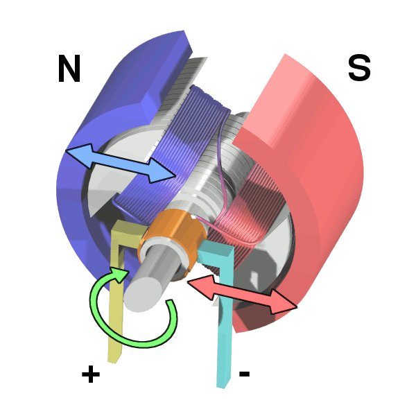
A brushed DC motor puts the windings on the rotor and uses a mechanical commutator to switch current as it spins. A split ring divided into segments, with two spring-loaded brushes rubbing against it, reverses the current through the winding every half turn. It is simple and self-commutating, however with the major disadvantage that the brushes rub against the split ring - causing friction and heat. This leads to brushes that eventually wear out.
A brushless DC motor inverts that arrangement. Permanent magnets sit on the rotor, the three-phase windings (U, V, W) sit on the stator, and the commutation that brushes used to do mechanically is now done by six MOSFETs arranged as three half-bridges, switched by a controller. Nothing rubs, so the motor lasts longer, runs cooler and has a much better torque-to-weight ratio. The cost is that the controller has to know where the rotor is, at all times, to energise the right coils at the right moment.
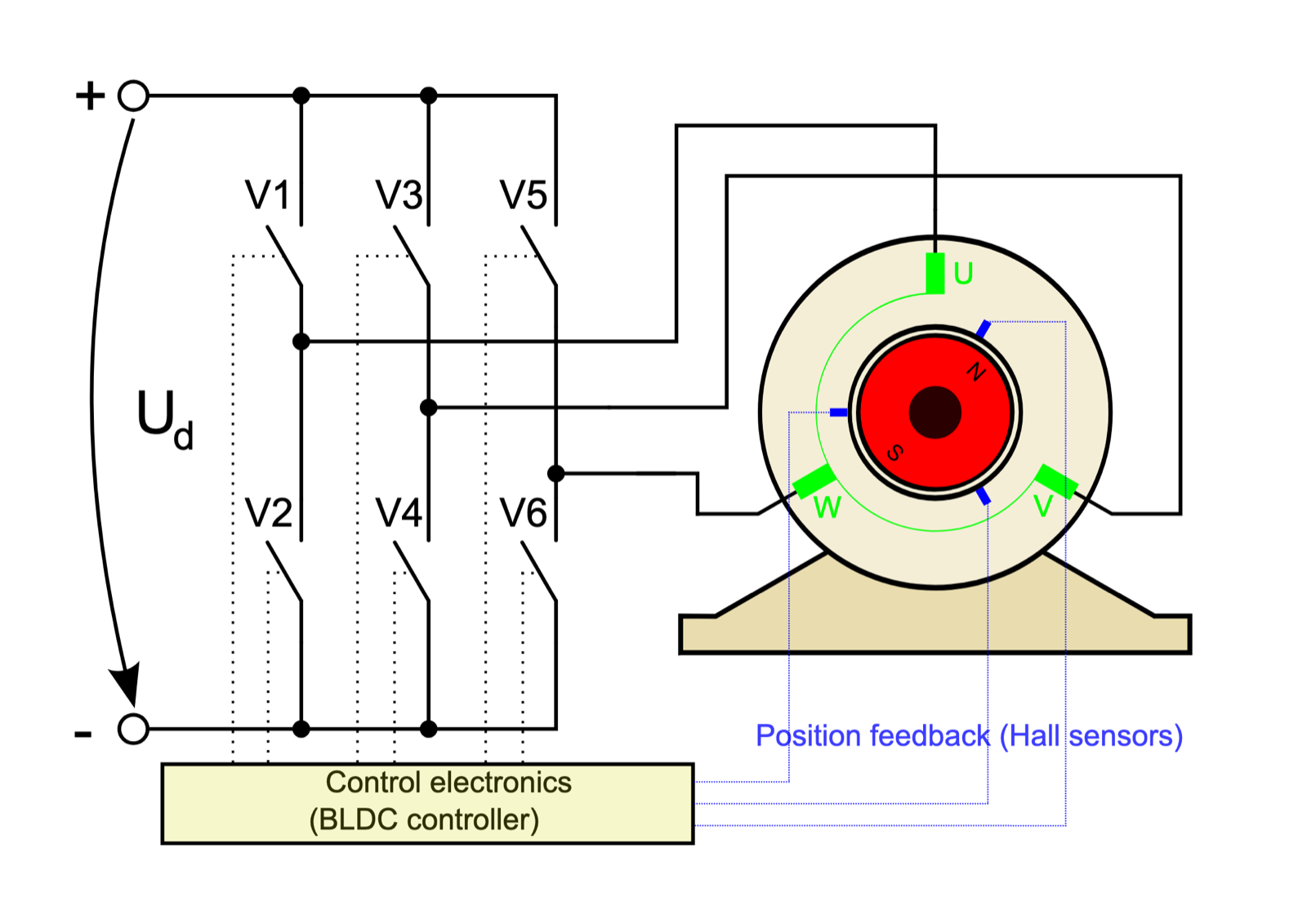
So rotor position (sensing + control) becomes the whole problem. How a controller answers it, and how precisely, is what separates a drone ESC from a robotics actuator.
The naive answer is six-step, or trapezoidal, commutation. Split one electrical revolution into six sectors, and in each sector drive one phase high, one low, and leave one floating. It works, it needs only coarse position information (three hall sensors, or back-EMF sensing on the floating phase), and it is what most cheap ESCs do. The problem is that the stator field jumps in 60° steps rather than rotating smoothly, which produces torque ripple, audible noise, and poor behaviour at low speed. At standstill, back-EMF sensing gives you nothing at all, so a sensorless six-step drive cannot hold position. For a drone that never matters. For an arm joint that has to sit still holding a load, it is disqualifying.
Field oriented control
FOC answers the same question properly. Instead of switching between six discrete states, it continuously computes the three phase voltages that place the stator's magnetic field exactly 90 electrical degrees ahead of the rotor's, which is the angle at which every amp of current produces the maximum possible torque.
The trick that makes this tractable is a change of reference frame. Working directly with three sinusoidal phase currents that all vary with rotor position is unpleasant. FOC transforms them into a frame that rotates with the rotor, where the quantities you actually care about become constants you can run a normal PI loop on.
The transforms
Clarke transform. Three phase currents into two orthogonal axes on the stator. Because the three phases sum to zero in a star-connected motor, they carry only two independent quantities, so no information is lost going from three axes to two. The result is a vector in a stationary frame, call the axes α and β.
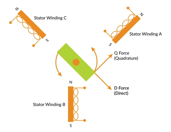
Park transform. Rotate that stationary vector by the rotor's electrical angle θ into a frame that spins with the rotor. This produces two values:
- i_d, the direct-axis current, aligned with the rotor's magnetic flux. This current pushes straight against the magnets. It produces no torque and mostly just heats the motor.
- i_q, the quadrature-axis current, 90° ahead of the flux. This is the component that produces torque.
That is the whole point of the exercise. In the d-q frame, a spinning three-phase problem collapses into two DC quantities, and torque control becomes: hold i_d at zero, and set i_q to whatever torque you want.
The loop
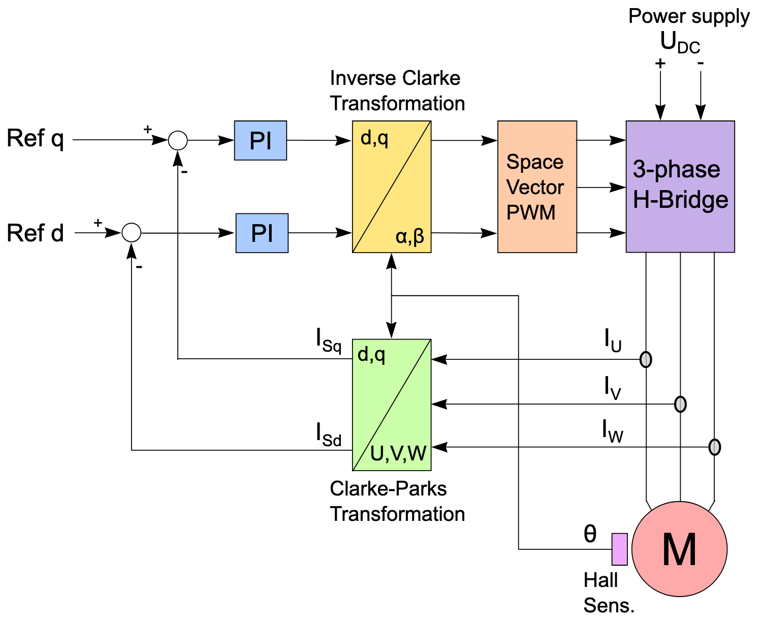
Each control cycle runs the same sequence:
- Measure two phase currents, derive the third.
- Read the rotor angle from the encoder.
- Clarke, then Park, to get measured i_d and i_q.
- Run a PI controller on each: i_d against a setpoint of zero, i_q against the torque demand.
- Inverse Park to convert the resulting voltage commands back to the stationary frame.
- Space vector modulation to turn those into the three PWM duty cycles that synthesise that voltage vector.
Around that inner current loop you can wrap a velocity loop, and around that a position loop, each feeding the setpoint of the one inside it.
Why the encoder decides everything
The diagram above takes θ from hall sensors, which is where most reference designs stop and where a robotics actuator cannot afford to. The Park transform needs θ, the rotor's electrical angle. If θ is wrong, the whole frame is misaligned: current that should have gone into i_q leaks into i_d, and you get less torque and more heat for the same amps. An angle error of a few degrees is a measurable efficiency loss. An error of 90° produces no torque at all.
This is why a good absolute encoder is not an accessory to an FOC actuator, it is a prerequisite. It also has to be fast, because the angle is consumed every single control cycle, and a stale reading at speed is the same thing as an angle error.
The FOC setup I built
The motor is a 2805 gimbal motor. Gimbal motors suit this application well: they are wound with many turns of thin wire, giving high torque at low current and low speed, which is what a joint wants, as opposed to the high-KV motors that drones want.
The motor was driven by a TMC6300 compact 3-phase brushless motor driver IC meant to operate at relatively low voltage and current. I paired it with a ESP32 for control. This was basically one of the cheapest entryways into the world of FOC at that time.
I used SimpleFOC to run position and velocity control on it. Starting from an existing library rather than writing the loop myself was deliberate: it let me get a working closed loop quickly, and see the behaviour of a real motor under real control, before taking on the firmware problem.
The setup worked perfectly for the size and class of motors I was intending to run on it. Open-loop tests worked fine, and then I moved onto the encoder boards for testing closed-loop control.
The encoder board
Closed-loop FOC needs absolute angle, available immediately at power-on, with no homing move. That rules out incremental optical encoders and points at magnetic absolute angle sensors, which reads the field of a small diametrically-magnetised magnet glued to the rotor shaft.
I built the feedback around the MA702, an absolute magnetic angle sensor with an SPI interface. SPI matters here: it gives a fast, deterministic read, so the control loop can fetch a fresh angle every cycle instead of waiting on a slower protocol or decoding a PWM output. I couldn't find any breakout boards for it available online, so I designed and printed the circuits for it and had it assembled from China.
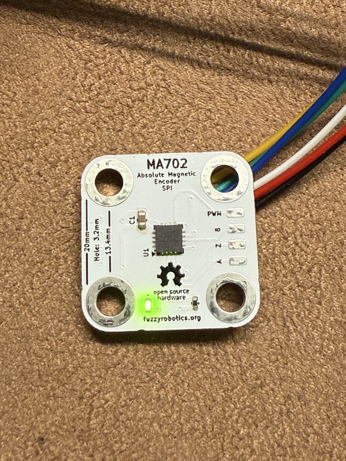
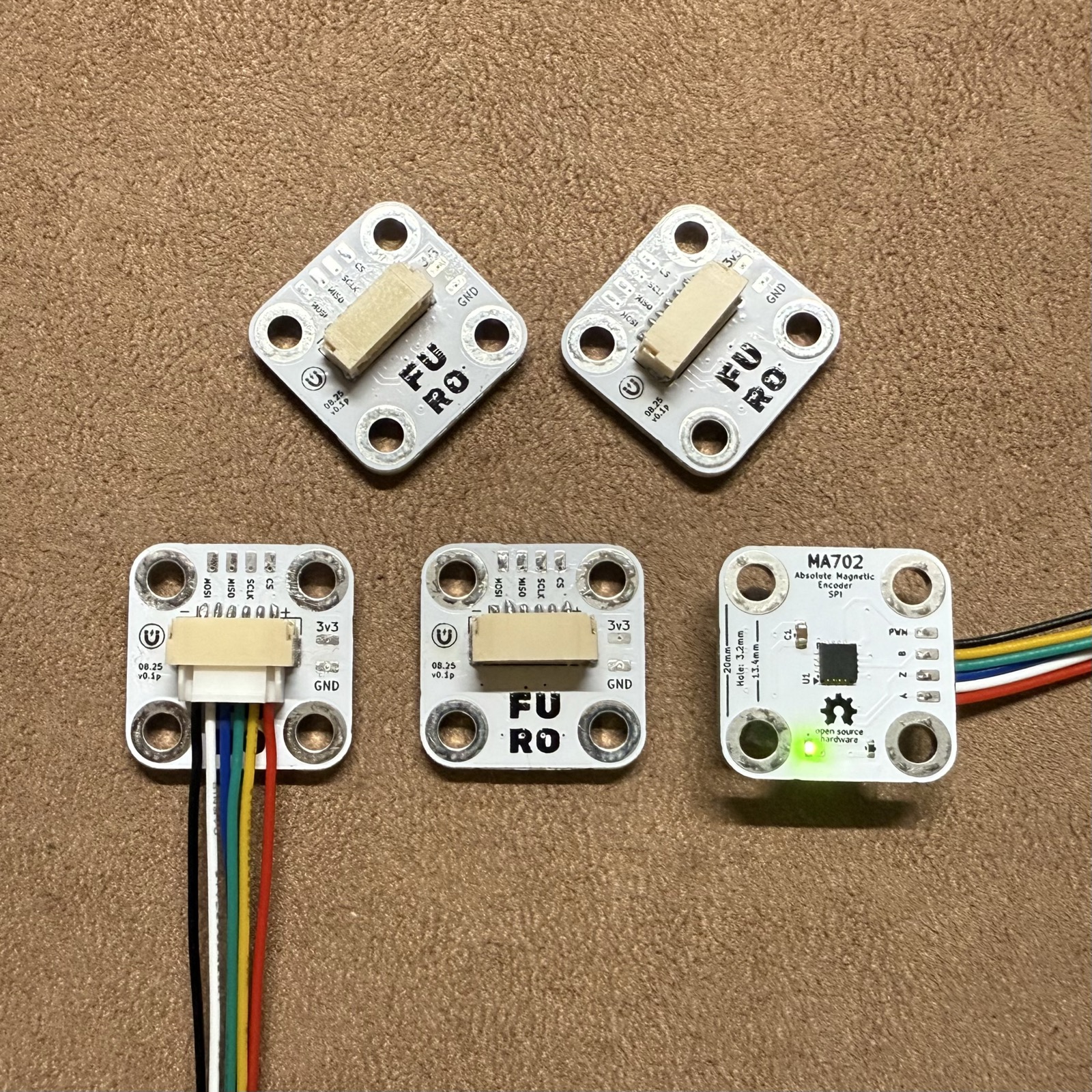
The board is 20 mm square with 3.2 mm mounting holes, bringing out MOSI, MISO, SCLK, CS, 3V3 and GND on a JST connector, with the sensor placed centrally so it sits directly over the magnet on the motor shaft.
Gear reduction
A gimbal motor spins faster and weaker than any arm joint wants. A gearbox trades that speed for torque: reduce the output speed by N and, minus losses, the output torque multiplies by N.
There is a second effect that matters just as much for a robot. Reduction also multiplies the reflected inertia of the motor as seen from the output, by N², which makes the joint stiffer and less prone to being back-driven by its own load. Too much of it and the joint stops being back-drivable at all, which is bad news for anything that has to be safe around people or sense contact through the motor.
The common options each fail differently at small scale:
- Spur gears are simple and easy to print, but a single stage puts the whole load on one pair of teeth, and input and output shafts are offset rather than coaxial.
- Worm drives give a large reduction in one stage and are usually non-back-drivable, which rules them out for a compliant arm.
- Cycloidal drives are compact with very low backlash and high shock tolerance, but need precise eccentric bearings that are hard to make well at this size.
- Planetary gearboxes share the load across several teeth at once, keep the input and output on the same axis, and stack cleanly. Which is why I used them.
How a planetary gearbox works
A planetary stage has four parts:
- a sun gear at the centre,
- three or more planet gears meshing with the sun,
- a ring gear with internal teeth that the planets also mesh with,
- and a carrier that holds the planet axles and rotates with them.
Any of the three rotating members can be input, output, or held fixed, which is what makes the arrangement flexible. The usual configuration for a reduction drive is: sun as input, ring held fixed to the housing, carrier as output. In that arrangement the reduction ratio is
ratio = 1 + (N_ring / N_sun)
where N is the tooth count of each gear. So a 4:1 stage needs a ring gear with three times as many teeth as the sun.
Two properties make this the right choice at small scale. First, torque is split across every planet simultaneously, so three planets each carry roughly a third of the load, and the gearbox survives forces that would strip a single spur pair. Second, the input and output are coaxial, so the whole stage is a cylinder with a shaft in and a shaft out, and stages can be chained end to end without any change in form factor. Chaining multiplies the ratios: two 4:1 stages give 16:1, three give 64:1.
My gearbox design
I designed the actuator as a set of modular, stackable modules: a motor module containing the 2805, and gearbox modules of 4:1 each, so the ratio is chosen by deciding how many to stack rather than by designing a new gearbox each time. The encoder board mounts at the bottom of the stack, reading the motor shaft directly.
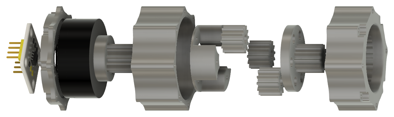
In each stage, the sun and planet gears have 12 teeth each, while the outer ring gear has 36 teeth. The carrier for one stage is either the output shaft, or attaches to the sun gear for the next stage. This enables the stackable feature of the gearbox system - each stage multiplies the ratio by 1:4. Each stage is just 16mm in height and fully contained. The stages can be screwed into each other directly.
The gearbox is made completely out of 3D printed parts, with the exception of screws and bushings for the planet gears. While not being durable enough for an entire robotic arm, the 3D printed actuator assembly actually holds up pretty well under load.
What is left
The main piece of unfinished work is replacing SimpleFOC with my own implementation of position, velocity and torque control, running on an STM32-based ESC dev board. SimpleFOC was the right way to get a loop closed and learn the behaviour, but writing the current loop, the transforms and the modulation myself is the point at which I will actually understand the control rather than just having configured it.
Whats also left is quantitatively measuring the actuator's properties like torque, speed and endurance. I did run it once for more that 48 hours continuously with a small load attached and it did fine - but better thorough testing is required.
This project has been on pause since 2025 since I left the relaxing life of a corporate job and went into startups - but I am trying to take out time to finish the project soon.